Frequently Asked Questions
- Other than providing cooling for pouch battery cells, can your technology provide cooling for other types of battery cells?
- For battery cells with low heat output or high heat tolerance, would passive cooling or air cooling be sufficient?
- What is the liquid used in your battery pack that is responsible for cooling?
- How is the coolant circulated?
- What are the ways to deal with leakage, overheating batteries, or damaged insulation?
- Can the dimensions of the battery pack be customized according to customer requirements?
- What is done to ensure that the surface of the battery cell and the multiple port tube (MPT) cooling surface are in tight contact?
- Is your technology too costly compared with air-cooled battery packs?
- What is the expected market positioning of your technology?
-
Other than providing cooling for pouch battery cells, can your technology provide cooling for other types of battery cells?
Pouch cells (flat with a laminated film covering) are most suited for our technology, as the multiple port tube (MPT) not only provides cooling, but offers a degree of mechanical support and protection.
Our technology can also employ prismatic cells (thick and rectangular with an aluminium or stainless steel casing). The hard outer casing offers additional protection. Compared to pouch cells, prismatic cells are heavier.
For larger Li-ion batteries containing smaller cells connected in series surrounded by an outer casing, these cells can be connected directly to our enclosure in parallel according to the required capacity, and then connected in series according to the desired voltage. This eliminates the need for the outer casing, which would have significantly impaired heat exchange.
Cylindrical cells are not suitable for our technology. As these cells have a small capacity, it would require a large number of cylindrical cells to constitute a battery pack. Also, because of its shape, a large amount of thermally conductive material is needed to fill the gaps. This results in significant complexities in construction and high cost.
-
For battery cells with low heat generation or high temperature tolerance, would passive cooling or air cooling be sufficient?
The thermodynamics of battery cells are ultimately governed by the principles of physics and chemistry. Regardless of the chemical composition of the cells, heat will be generated by both electrical resistance and the chemical reactions taking place within the cell. Improvements in the battery technology can only minimally reduce heat generation. Negating heat production is impossible unless the material is a superconductor at room temperature.
When charging or discharging at high currents (eg. at 200A when an electric vehicle is driving up a slope, accelerating, making use of its kinetic energy recovery, or undertaking fast charging), the resistance alone of the battery is already significant in producing heat (W=I²R).
During summer, when ambient temperatures can reach 40ºC, passive cooling or air cooling is unable to adequately cool the battery to its optimal temperature of 15-35ºC. The safety, performance, and longevity of the battery cells will thus be affected. During winter, the use of electrical heating films is associated with long heating times and non-uniform heating.
Our technology allows for both cooling and heating in a fast and efficient manner while keeping temperature variations between battery cells to a minimum. This reduces burden and energy expenditure of the battery management system (BMS) in balancing the pack. It allows the battery cell temperature to be maintained at its optimal temperature range of 15-35ºC, improving safety, performance, and longevity. This is especially important for high capacity battery packs.
-
What is the liquid used in your battery pack that is responsible for cooling?
It is a 50:50 mixture of water and ethylene glycol, which is a common coolant used in most automotive applications. It has a freezing point of -34ºC (meaning it does not freeze in winter), and a boiling point of 107ºC.
Heat is transferred from the batteries to the coolant (or vice versa if the batteries need to be heated), which will be connected to the vehicle’s air conditioning system and the heat exchange system for heat dissipation. This is covered in more detail in the subsequent point under ‘Flow of coolant within the broader vehicle system‘.
-
How is the coolant circulated?
- Flow of coolant within the battery pack
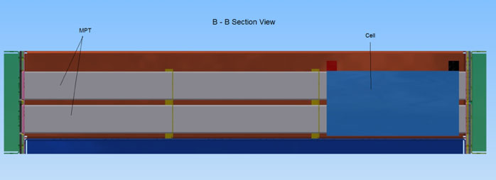
Rubber sheets with different cut-out arrangements are sandwiched between front and back covers/ end-plates, so as to guide the flow of coolant to distribute it throughout the enclosure. This ensures efficient and uniform cooling of all surfaces of the battery cells in the pack.
The patent filings offer a comprehensive explanation of the coolant flow.
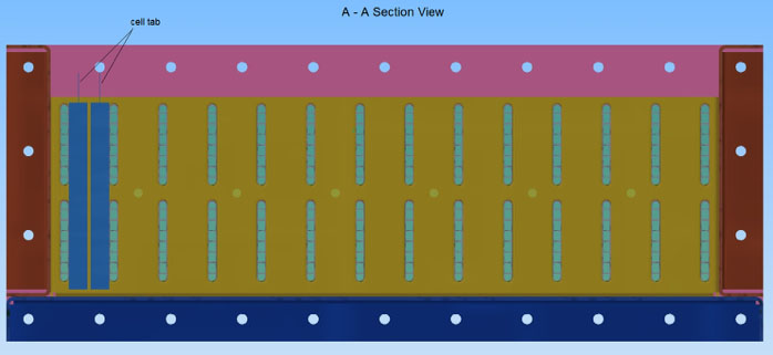
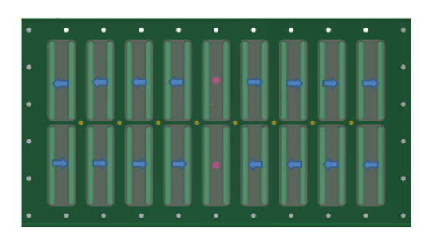
The arrows in the following images illustrate the direction of coolant flow from various views.
Front rubber cut-out with front cover (transparent)
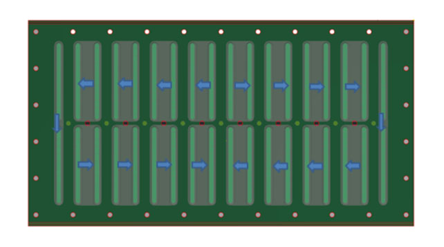
Back rubber cut-out with back cover (transparent)
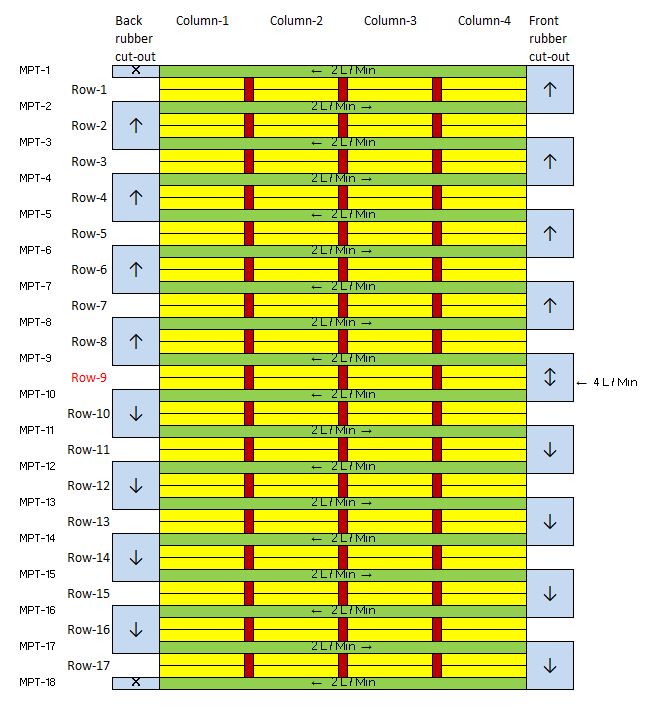
Coolant flow diagram in top layer of MPT
2. Flow of coolant within the broader vehicle system
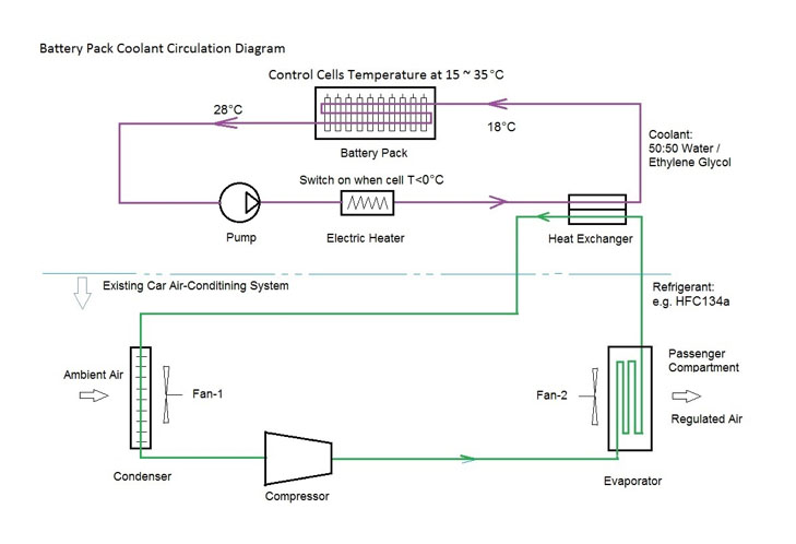
The above schematic illustrates a basic cooling/ heating circuit. When applied to an electric vehicle, the only modification is the addition of a heat exchanger, which is a relatively simple process.
When there is no need to start the vehicle air-conditioning, only the compressor is needed to be started to cool the battery during high-current charging or discharging. The air-conditioning fan in the car interior (Fan-2) need not be started. Energy is saved as no heat exchange takes place with the interior of the car.
When the ambient temperature permits, or when the car is being driven, the condenser or the radiator alone can be sufficient to dissipate heat into the ambient air. Fan-1 might not be required to be turned on, saving energy.
A heat pump can replace electric heaters used for heating.
-
What are the ways to deal with leakage, overheating battery cells, or damaged insulation?
The surfaces of our battery enclosure are anodized. Insulating paint or other surface treatments can be applied if necessary to ensure insulation between the battery cells and the enclosure.
There are also appropriate measures for shock absorption and cushioning between the battery cells and the enclosure.
The coolant circuit is also equipped with a gas sensor for micro-leaks, temperature sensors on each battery cell, and real-time detectors for high-voltage insulation resistance. In the event of leakage, overheating of battery cells or thermal runaway, or damaged insulation, alarms will be set off which will then notify the driver. The system can also be customized to communicate with mobile phones or other systems so as to notify the vehicle owner or maintenance staff regarding any issues.
Current battery packs in the market only utilize 4-5 temperature sensors in the entire pack. In our battery pack, with real-time monitoring of the temperature of each cell, alarms triggered by any anomalies detected can lead to a prompt response, minimizing the risk of serious complications such as thermal runaway, preventing fires and any loss of life or limb.
-
Can the dimensions of the battery pack be customized according to customer requirements?
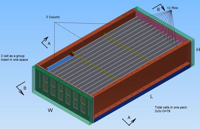
Yes. The dimensions of the enclosure can be customised while ensuring maximum battery cells in a limited space.
According to customer requirements in the type and size of battery cells, we can customize
- MPT row spacing (dependent on battery cell thickness)
- enclosure column spacing (dependent on battery cell width)
- enclosure height and number of layers of MPT (dependent on battery cell height)
- the overall dimensions of the enclosure (dependent on the total number of battery cells/ total capacity kWh)
-
What is done to ensure that the surface of the battery cell and the multiple port tube (MPT) cooling surface are in tight contact?
A pressurised air bag is sandwiched between every pair of battery cells. Pressure from the air bag ensures uniform contact of the battery cells with the MPT cooling surface. This not only improves heat exchange efficiency, but also accommodates for any swelling of the battery cells. It also functions as a cushion for shock absorption.
The air bag system is illustrated in this diagram:
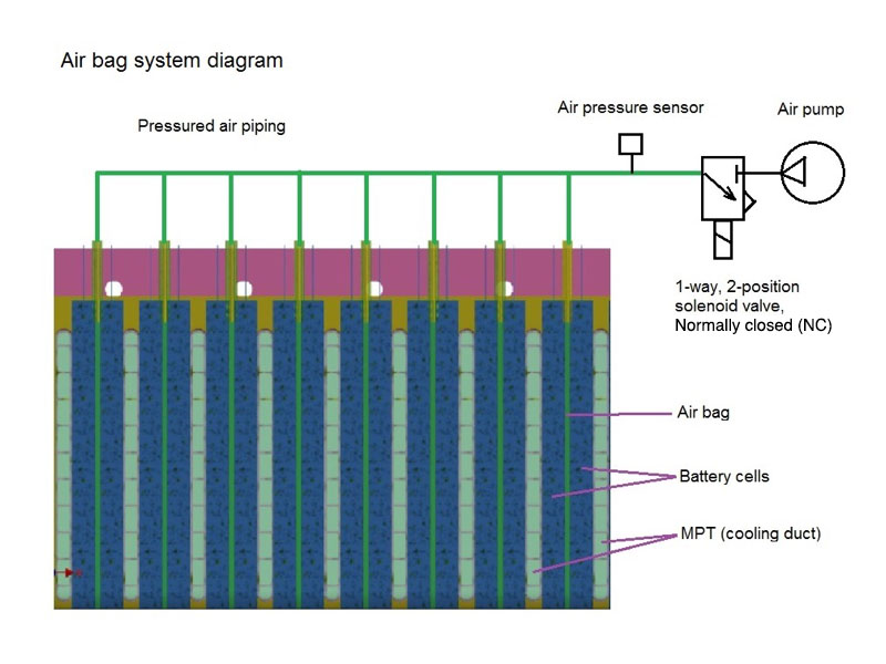
Upon initiating the battery management system (BMS), the air pressure sensor will detect the pressure within the air bag system. If the air pressure falls below a pre-defined P1 at any point of time, the air pump will be turned on with the solenoid valve open. The air pump is stopped when the air pressure goes above a pre-defined P2, with the solenoid valve closed.
To accommodate for swelling of the battery cells, the solenoid valve will be open with the air pump turned off when P2 is reached. This allows the leak of air to relieve the pressure. The solenoid valve is closed when P1 is reached.
If the system fails to reach P2 for a prolonged period of time, this indicates a leak in the system, triggering an alarm. If the air pump is found to be turned off for long periods of time with the solenoid valve open, this indicates widespread battery cell swelling, signalling a need to change battery cells.
-
Is your technology too costly compared with air-cooled battery packs?
This is a common misconception from customers viewing our technology for the first time.
In comparing our battery pack with one of the same capacity and power requirements, our technology has a 17% lower initial cost (including the enclosure, battery cells, battery management system, and cooling system), with further cost savings from increased battery life expectancy and reduced maintenance needs. This is achieved by simplifying the traditional battery pack design with the elimination of the module level.
From repeated experiments and trials in the manufacturing process, we have found that our technology is suitable for mass production while ensuring consistent quality with low costs. There are also no engineering difficulties encountered.
The enclosure is constructed with multiple port tubes (MPTs) with the use of continuous atmospheric brazing to join the MPT with the enclosure. This produces a strong enclosure which is also lightweight and small.
-
What is the expected market positioning of your technology?
Our technology involves an integrated liquid-cooled battery enclosure. This can be combined with most existing battery cell technologies in the market to provide a complete battery pack product. Our technology is not meant to compete with existing battery cell manufacturers and battery pack providers, but instead complement and increase the competitiveness of their existing products. If needed, a complete battery pack solution can also be provided in conjunction with our partners.